Back to BRIDGframe Page 1
|
|
 |
|
| User Interface - Other Tabs |
|
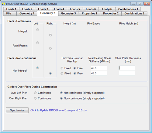
Geometry 2
- used to input the geometry of the Abutments and Piers
- used to define Continuous or Semi-continuous superstructures by inputting girder condition over piers during construction
- for non-continuous piers, forces from bearings and application of load at bottom of shoe plate can be included in the analysis
|
 |
| |
|
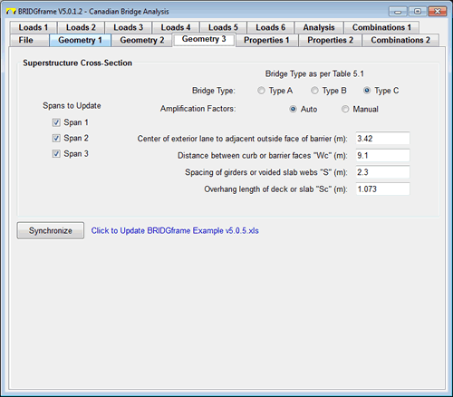
Geometry 3
- used to establish the Live Load Girder Distribution Factors
- input for Spans may be grouped to simplify data input
- different design parameters for each span may be specified
|
 |
| |
|
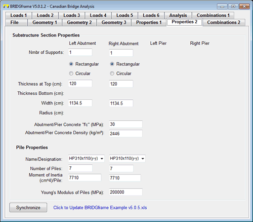
Properties 2
- used to input the properties of the Abutments, Piers and Piles
- not applicable to non-continuous Abutments and Piers
- section properties are automatically generated
|
 |
| |
|
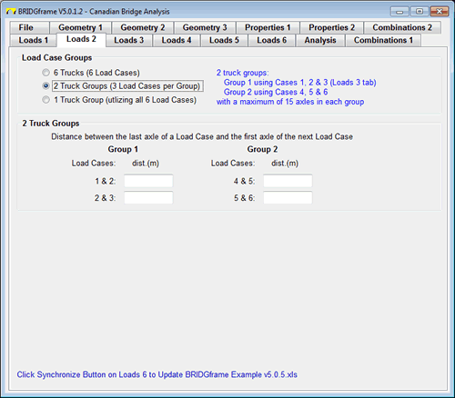
Loads 2
- define location of each truck load case relative to each other
- allows generation of up to 6 single vehicles passing over the structure independently
- alternatively vehicles may be grouped and then together passed over the structure. 2 groups of 3 vehicles each with up to 15 axles per vehicle or 1 group of 6 vehicles with up to 30 axles may be created
|
 |
| |
|
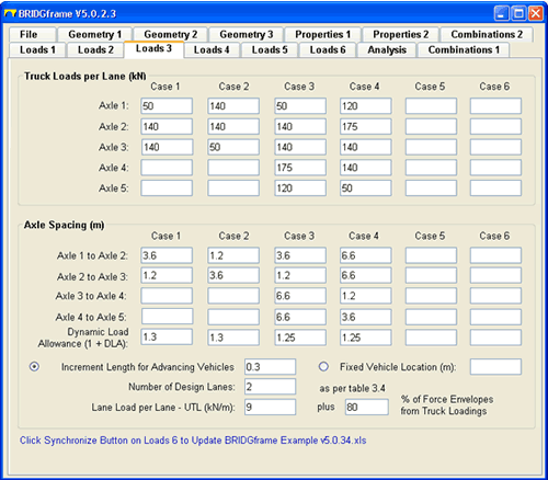
Loads 3
- used to input the Truck Loads and Lane Loads per Lane
- a total of 6 vehicle load configurations may be analyzed in any one run
- all Truck Load Cases and Truck/Lane combinations are automatically compared
|
 |
|
|
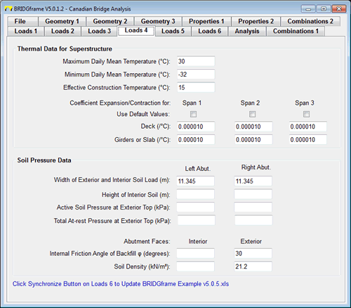
Loads 4
- used to define Thermal and Soil Pressure Data for Superstructure
- automatic generation of default values for coefficients
- initial Soil Pressure required only; changing pressures during movement are automatically generated
|
 |
| |
|
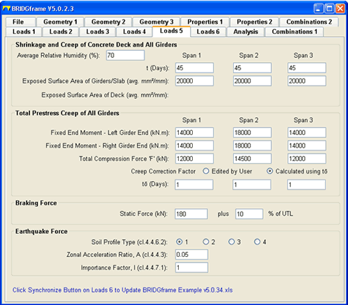
Loads 5
- used to define Shrinkage & Creep of Superstructure Deck and Girders
- used to input prestressing forces for Prestressing Creep Restraint effects
- automatic generation of Dead Load Creep Restraint effects
- input of Braking and Earthquake data for longitudinal force effects
|
 |
| |
|
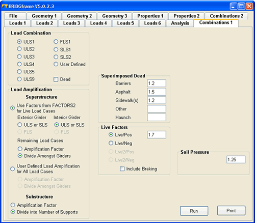
Combinations 1
- user defined or CSA-S6-S14 load combinations
- user defined or CSA-S6-S14 load amplification (distribution) to Exterior and Interior design strips or girders
- user defined distribution of loads to substructures
- generates combination for loads on naked girder or composite girder using one model
|
 |


